Calibration Procedures
CALIBRATION PROCEDURE
Some repairs performed on the Cat Synthesizer will necessitate recalibration
of the unit. This is
especially true if repairs have been performed on either the control
voltage processors,
the VC0 exponential current converters, the 6.2 volt reference, or
the power supply.
Calibration of the unit is accomplished by the adjustment of several
trimmers accessible through
holes in the front panel. In order to gain access to the calibration
trimmers, the plastic
plugs must first be removed from the holes. This is most easily accomplished
by pushing the plugs
out from the inside of the chassis with the circuit boards removed..
Removal of the plugs
by prying them from the front panel is not recommended.
To properly calibrate the Cat Synthesizer a high impedance digital voltmeter
of at least 3 1/2
digits is required, A digital frequency counter is helpful, but not
required to calibrate the unit. A
frequency standard such as a tuning fork, strobe tuner, or another
calibrated synthesizer is
necessary in order to perform calibration on a Cat Synthesizer.
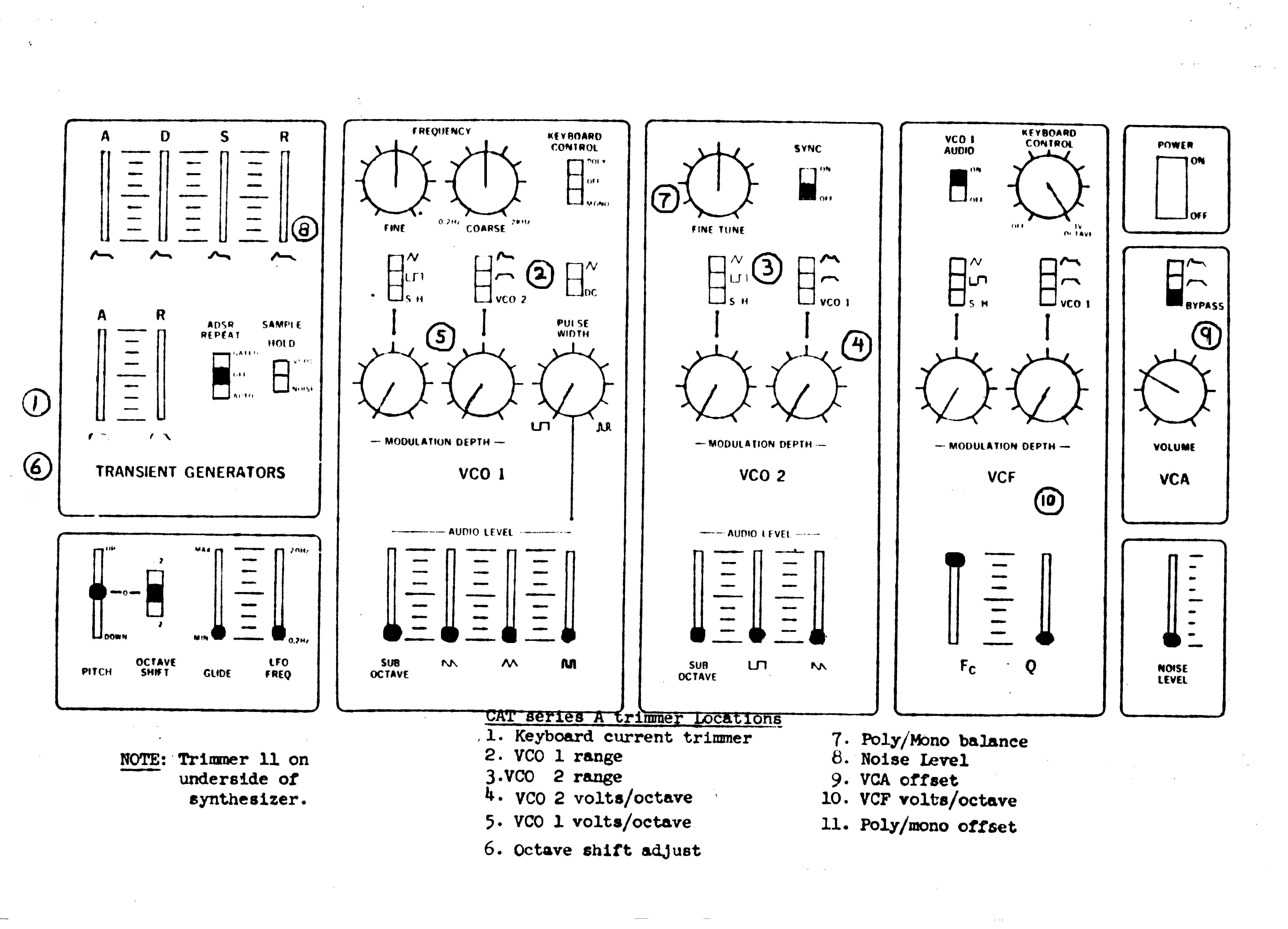
Set the panel controls as shown in Fig. 1 and perform the calibration steps in the sequence listed,
Step 1 KEYBOARD CURRENT ADJUSTMENT
a. Set trimmer (11) under the keyboard fully CLOCKWISE so that the keyboard
resistive divider
chain reads a minimum resistance of 3.6K.
b. Set the keyboard current trimmer (1) so that the voltage at the top
of the keyboard resistive
divider reads +3.000 volts with the highest C note depressed. This
voltage should be measured
with a high impedance DVM at the control voltage bus located on the
keyboard connector.
Consult the wiring harness layout for the pin location of the CV bus
on the keyboard
connector. When properly adjusted, the highest C note depressed will
yield +3.000 volts,
decreasing by exactly by 1.000 V per octave or 83 mV per half step.
c. After adjustment of the keyboard current trimmer (1) for 1.000 V
per octave response, readjust
the keyboard trimmer (11) so that the voltage reads approximately +4,00,
measured as in
step b.. This wilI require turning the trimmer by about 2/3 of its
range in a
COUNTER-CLOCKWISE direction.
Step 2 VCO 1 RANGE
a, Turn down all or the audio sliders except for the VCO 1 sawtooth
amplitude Set the
FREQUENCY CONTROLS for VCO I to the 12 O"Clock position with the KEYBOARD
CONTROL in the MONO position. Check that the PITCH BEND and OCTAVE
PITCH are
in the "0" position and that all modulation sources are fully off,
b. Depress the A above middle C (i.e. the second A note from the bottom
or the keyboard) and
adjust the VCO 1 range trimmer (2) until the VCO 1 frequency is approximately
440 Hz.
Step 3: VCO 2 RANGE
a. With the same set-up as in step 2, turn up the VCO 2 sawtooth slider
so that both VCO 1 and
VCO 2 are audible.
b. Set the VCO 2 TUNE CONTROL to the 12 O"Clock position and adjust
the VCO 2 range
trimmer (3) so that VCO 1 and VCO 2 are at zero beat with the middle
A note depressed.
Step 4: VCO 2 VOLTS/OCTAVE
Using a frequency counter
a. Turn up the VCO 2 sawtooth slider so that only the VCO 2 sawtooth is used,
b. Tune VCO 2 to 1000 Hz with the highest C depressed.
c. Depress the lowest C note and adjust the VCO 2 V/Oct. trimmer (4)
until the counter reads
125 Hz (3 octaves below l000Hz),
d. Depress the high C again and readjust the TUNE CONTROL to l000Hz,
e. Repeat these steps until no adjustment of the Volts per Octave trimmer
is necessary to obtain
1000 Hz on the high C note and 125 Hz on the low C note.
Without a frequency counter
a. Turn up the VCO 2 sawtooth slider so that only the VCO 2 sawtooth is audible.
b. Depress the highest C note and tune VCO 2 to approximately 1000Hz,
c. Place the VCO 1 KEYBOARD CONTROL in the OFF position and turn up
the VCO 1
sawtooth slider.
d. Using the VCO 1 FREQUENCY CONTROLS tune VCO 1 to VCO 2 until zero beat occurs.
e. Depress the low C and adjust the VCO 2 Volts/Octave trimmer (4) until zero beat is heard.
f. Depress the high C again and retune VCO 1 to VCO 2 as in step d.
g. Repeat steps d, e, and r until no further adjustment of the VCO 2
Volts/Octave trimmer is
necessary.
Step 5: VCO 1 VOLTS/OCTAVE
Using a frequency counter
a. Place the KEYBOARD CONTROL in the MONO position and bring up the
VCO 1 sawtooth
slider.
b. Tune VCO 1 to 1000 Hz with the highest C depressed.
c. Depress the lowest C note and adjust the VCO 1 Volts/Octave trimmer
(5) until the counter
reads 125 Hz (3 octaves below 1000 Hz).
d. Depress the high C again and adjust the FINE TUNE control to 1000 Hz.
e. Repeat these steps until no adjustment of the Volts per Octave trimmer
is necessary to obtain
1000 Hz on the high C note and 125 Hz on the low C note.
Without a frequency counter
a. Assuming VCO 2 Volts/Octave has been calibrated, we can calibrate
VCO 1 using VCO 2 as a
reference. Place the KEYBOARD CONTROL in the MONO position and turn
up both the
VCO 1 and VCO 2 sawtooth sliders,
b. Depress the high C and using the VCO 1 FREQUENCY CONTROLS tune VCO
1 to VCO 2
until zero beat is achieved.
c. Depress the low C and adjust the VCO 1 Volts/Octave trimmer (5) until
zero beat between
VCO 1 and VCO 2 is heard.
d. Repeat steps b and c until further adjustment of the VCO 1 Volts/Octave
trimmer is no longer
necessary.
Step 6: OCTAVE SHIFT ADJUSTMENT
Using a frequency counter
a. Place the OCTAVE SWITCH in the '0' position and turn up only the VCO 1 sawtooth slider,
b. Tune VCO 1 to 250 Hz using the COARSE and FINE CONTROLS.
c. Place the OCTAVE SWITCH in the +2 position and adjust the octave
trimmer (6) until VCO 1
has an output frequency or 1000 Hz (2 octaves above 250 HZ),
Without a frequency Counter
a. Turn up the sawtooth sliders on both VCO 1 and VCO 2.
b. Place the KEYBOARD CONTROL in the OFF position and tune VCO 1 to
VCO 2 with the
highest C note depressed using the FINE and COARSE controls.
c. Place the OCTAVE SWITCH in the +2 position and depress the C note
two octaves down
from the highest C note on the keyboard.
d. Adjust the octave trimmer (6) until VCO 1 and VCO 2 are at zero beat.
Step 7: POLY/MONO BALANCE
Using a frequency counter
a. Set the KEYBOARD CONTROL to the POLY position with only the VCO 1
sawtooth slider
turned up.
b. Hold down the highest C note and tune VCO 1 to approximately 1000 Hz,
c. Depress the lowest C note while still depressing the high C note
and adjust the POLY/MONO
BALANCE trimmer (7) so that there is little or no change in frequency
when the high C note is
depressed alone and when both the high and low C notes are depressed
together.
Without a frequency counter
a. Place the KEYBOARD CONTROL in the POLY position and tune VCO 1 to
VCO 2 with the
high C depressed.
b. Simultaneously depress both the highest and lowest C notes on the
keyboard and adjust the
POLY/MONO BALANCE trimmer (7) until zero beating is heard.
c. Repeat steps a and b until there is no beating between VCO 1 and
VCO 2 with only the high C
depressed and with both the highest and lowest C notes depressed simultaneously.
Step 8: FINAL KEYBOARD TRIMMER ADJUSTMENT
a. Place the KEYBOARD CONTROL switch in the MONO position and tune VCO
1 and VCO 2
together at about 1000 Hz with the high C note depressed and the PITCH
BEND slider and
OCTAVE SWITCH both in the '0' position.
b. Place the KEYBOARD CONTROL in the POLY position and adjust trimmer
(11) until VCO 1
and VCO 2 are again in tune. There should be little or no pitch change
in VCO 1 when the
KEYBOARD CONTROL switch is alternated between the MONO and POLY positions.
Step 9: NOISE LEVEL ADJUSTMENT
a. Connect an oscilloscope to the output and turn the noise level slider fully up.
b. Adjust noise level trimmer (8) for maximum noise output before clipping occurs.
Step 10: VCA d.c.. OFFSET ADJUSTMENT
a. Turn all audio sliders to the off position and turn the VCA volume knob fully clockwise.
b. Set the modulation switch on the VCA to the ADSR position.
c. Set thm ADSR REPEAT SWITCH to the AUTO position with the S slider
of the ADSR fully
up.
d. Set the LFO FREQUENCY slider to the MAXIMUM frequency position and
adjust the VCA
offset trimmer (9) for minimum thumping at the output.
Step 11: VCF VOLTS/OCTAVE
a, Turn up the "Q" control on the VCF so that the filter is in oscillation.
Set the filter cutoff
frequency to about 1000 Hz with the KEYBOARD CONTROL VOLTAGE KNOB full
up to
the 1 V/Octave position and the highest C note depressed.
b. Alternately depress the highest C note and the C one octave below
the highest C and turn the
Volts/Octave trimmer (10) until an octave interval is heard between
these two notes.
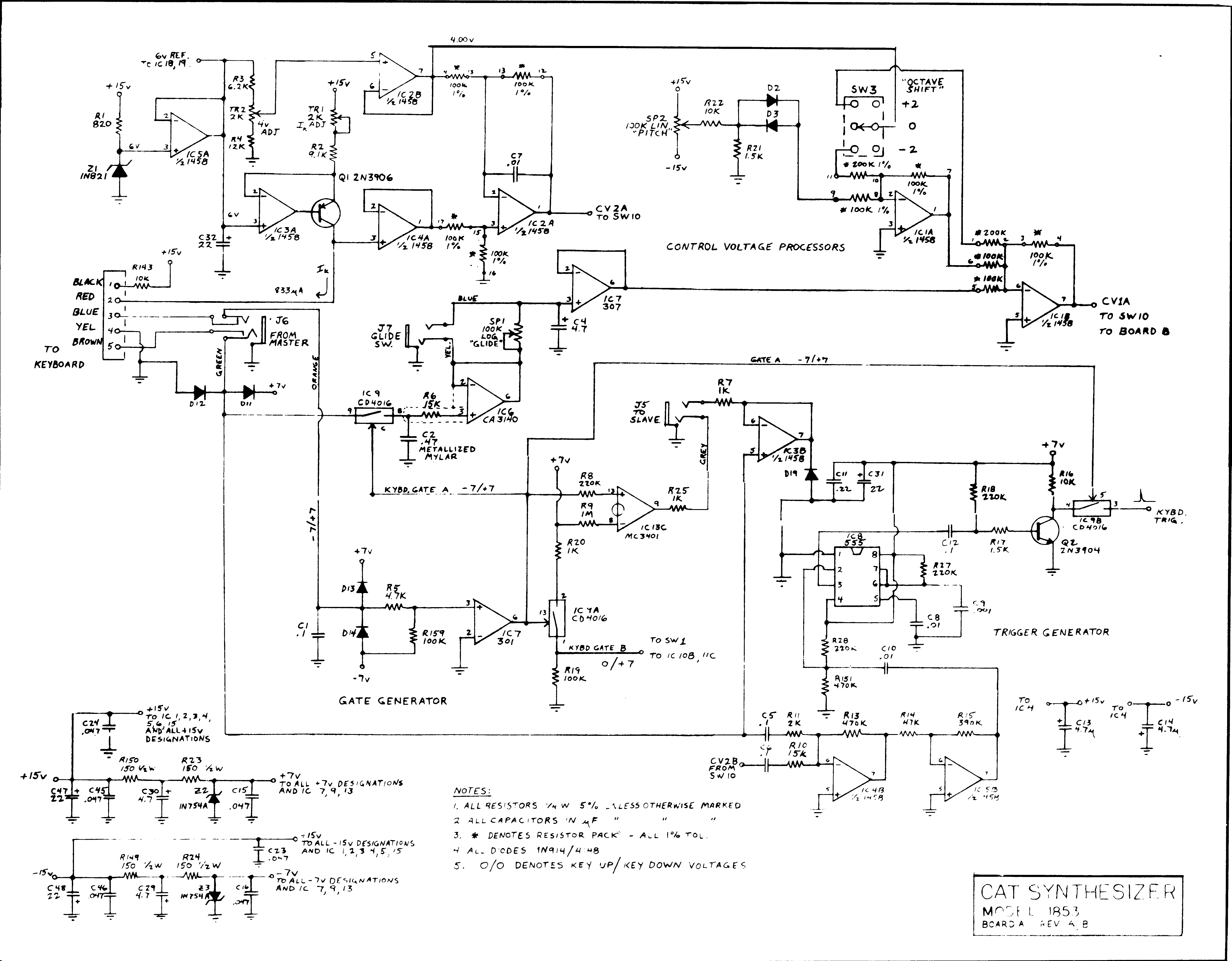
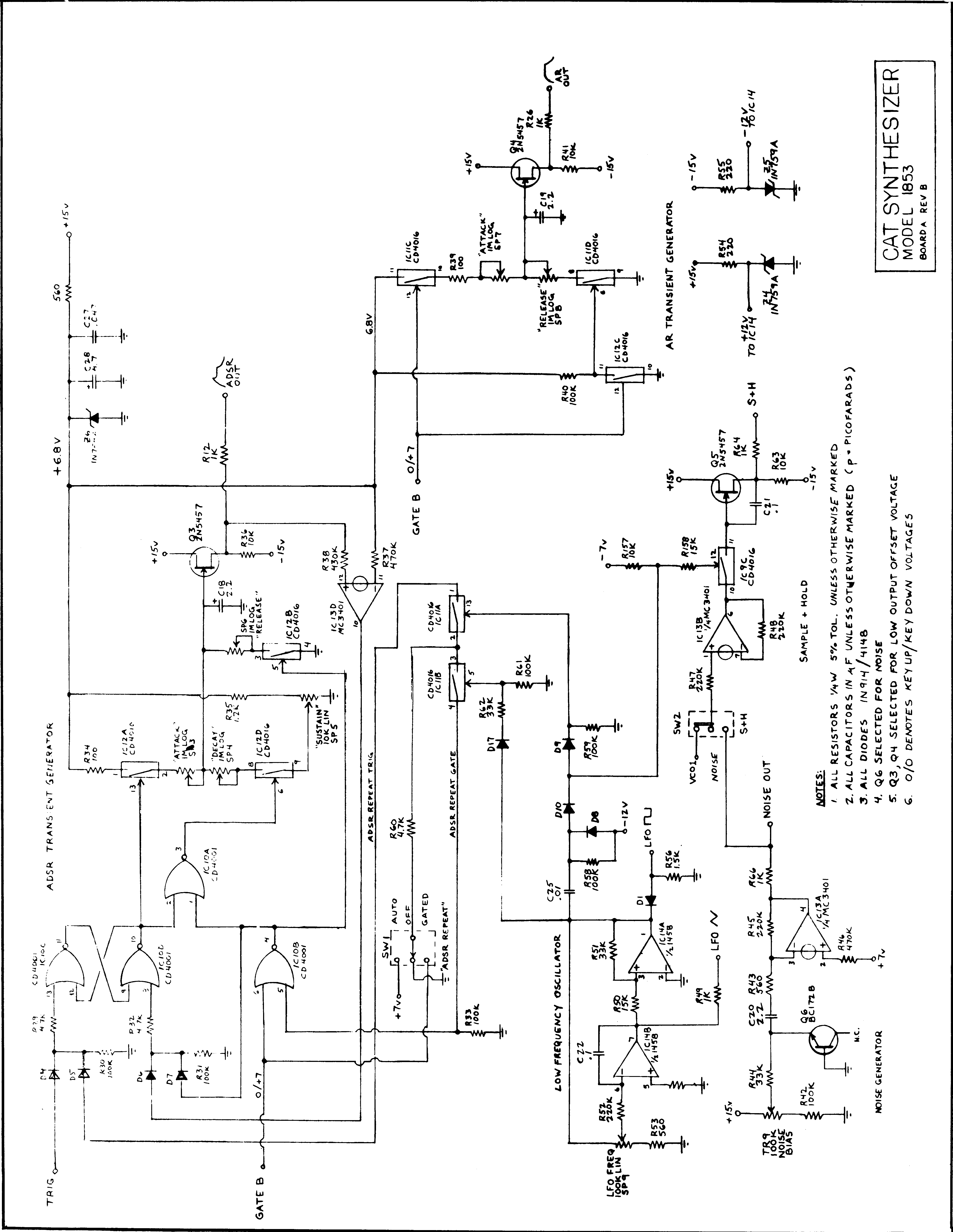
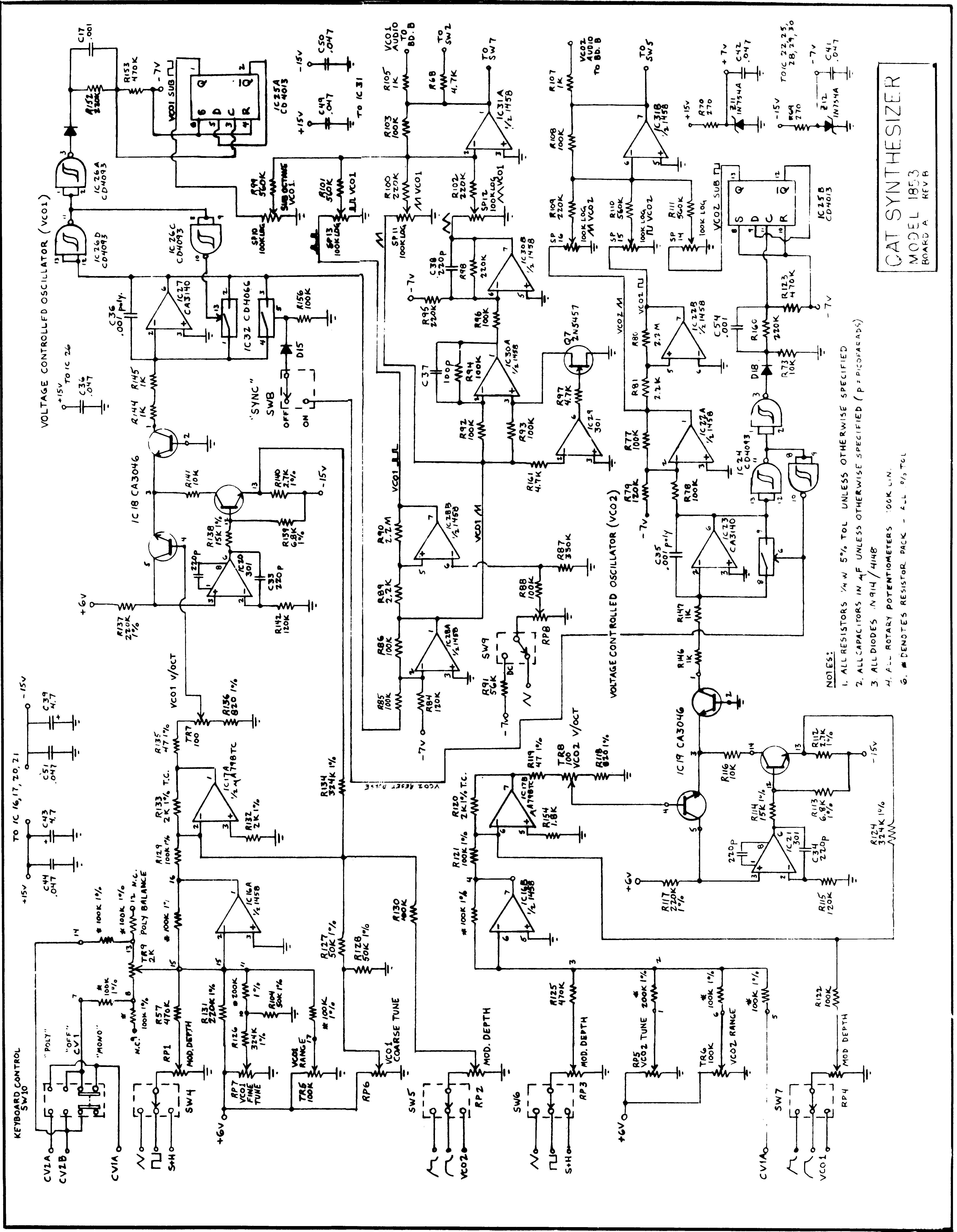
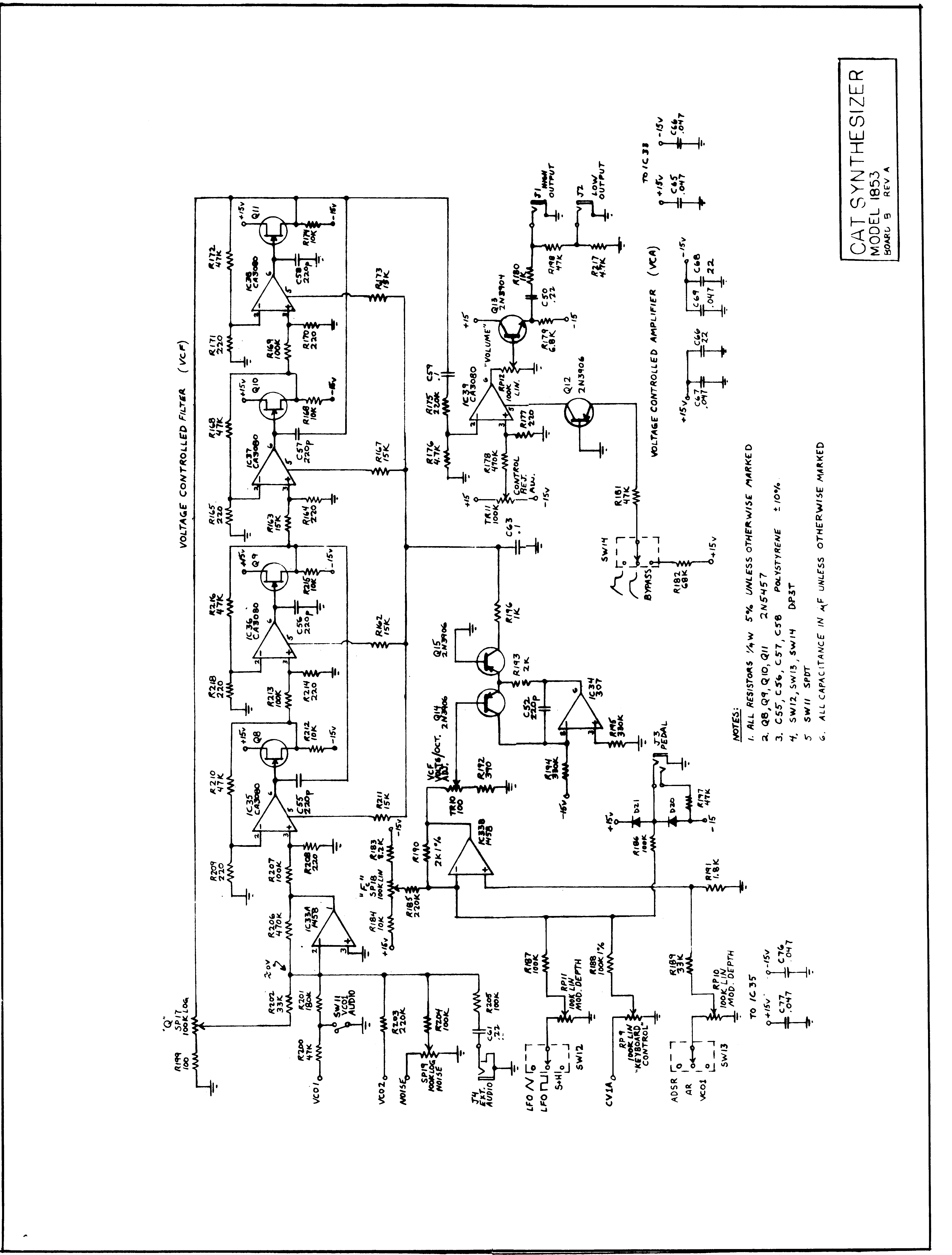
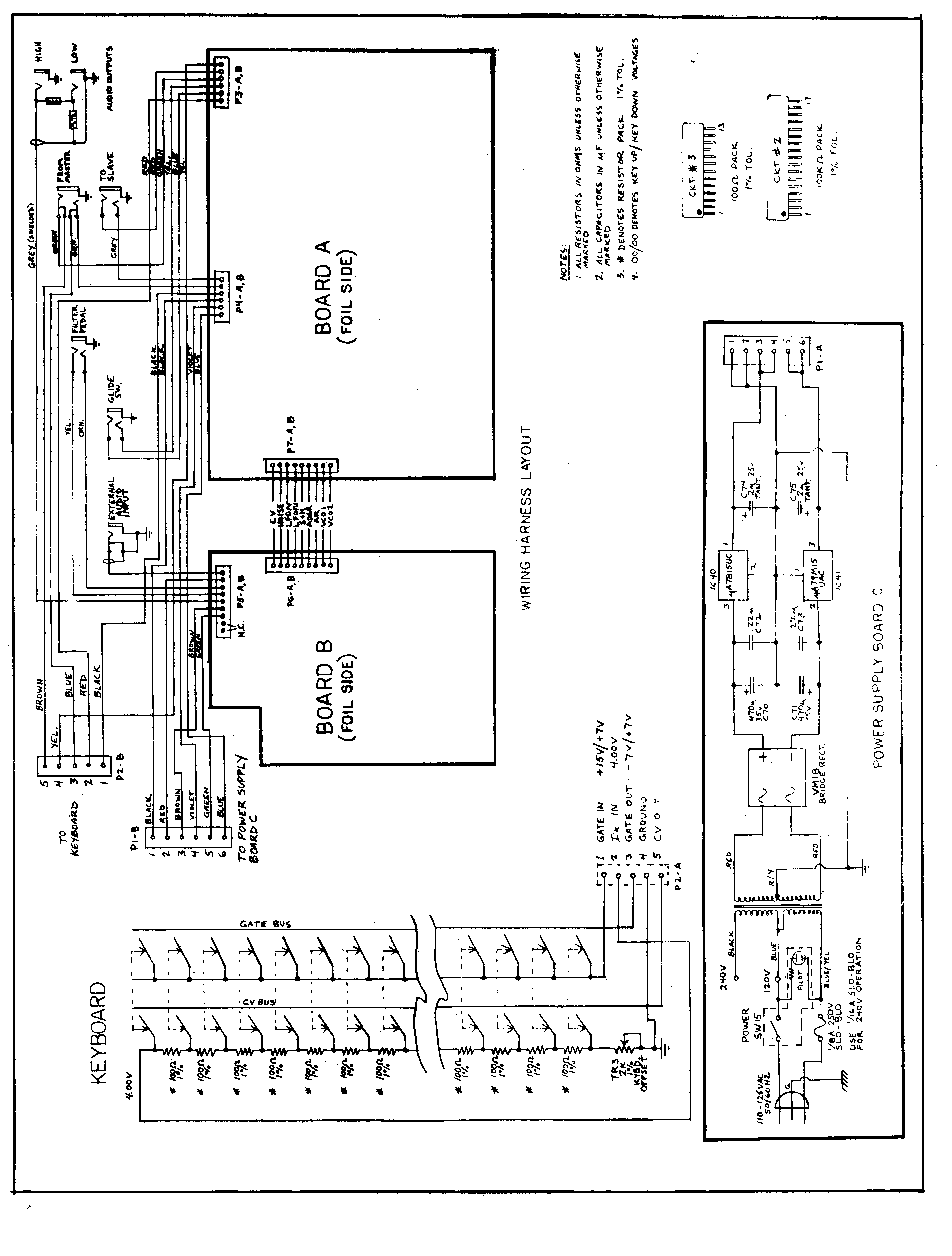
Schematic #1 / Schematic #2 / Schematic #3/ Schematic #4/ Schematic #5
PDF Files
Schematic #1 / Schematic #2 / Schematic #3/ Schematic #4/ Schematic #5
Visits since 07/05/2002
E-Mail me at: